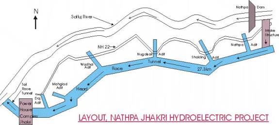
THE PROJECT
General
The Nathpa
Jhakri Hydro-electric project, located in Kinnaur and Shimla districts of
Himachal Pradesh, is a run-off the river type development, proposed to harness
hydroelectric potential of the upper reaches of the river Sultej, the project
proposed to generate about 1500 MW, is one of the biggest underground ventures
in the world. Figure gives schematic
diagram of the project layout. The
Nathpa-Jhakri power corporation was incorporated on 24th May 1988 as
a joint venture of the Government of India and Government of Himachal
Pradesh. The economic hydropower
potential of Himachal Pradesh has been assessed as more than 20,000 MW of
installed capacity. The potential
developed so far is only about 3000 MW (15%) while 1200 MW (6%) is under
development. River Sutlej has the
pre-eminence of hydropower potential of over 9350 MW, of which only 1330 MW
(14%) has so far been harnessed.
Salient
Features
(i) Location
|
State |
Himachal
Pradesh |
|
District |
Kinnaur
/Shimla |
|
Vicinity
|
Dam
down stream of Wangu bridge of Nathpa and power house near Jhakri Village on left bank of river
satluj. |
|
ii) Hydrology |
|
|
Catchment area of river Satluj at Dam
site. |
49,820
Sq. Km. |
|
Dependable year run off |
7720
million cubic metres |
|
Mean year run off |
9840
million cubic metres. |
|
Design discharge |
405
cumecs. |
|
Design flood |
5660 cumecs |
|
iii) Dam |
|
|
(a) Type of
dam |
Concrete,
gravity |
|
Maximum height above foundation level |
60.5
m |
|
Length of dam at road level |
17.20
m |
|
Top of dam |
El.
1493.50 m |
|
Maximum water level |
El.
1490.50 m. |
|
Minimum drawndown level |
El. 1474.00 |
|
Pondage available |
457
hect. meters |
|
b) Under Sluices |
|
|
Design flood |
5600
cumecs |
|
Crest level |
El.
1458.00 m |
|
Gates |
6
radial gates each of size 7mx7.35 m |
|
Energy dissipation |
Ski
jump |
|
c) Spilway for
maintaining MWL |
|
|
Crest level |
El.
1488.00 m |
|
Gates |
2
counter weight balanced gates each of size 7.5 mx2.5 m. |
|
Energy dissipation |
Ski
jump |
|
iv)
Desitling Arrangement |
|
|
Type |
Underground |
|
Number and size |
Four
parallel chambers ach 525 m long, 63 m wide at the centre and 27.5m deep. |
|
Flow through velocity |
33.4
Cms/Sec. |
|
Particle size to be removed |
Particles
greater than 0.2 mm. |
|
|
|
|
Shape |
Circular,
Concrete lined |
|
Length |
27295
m |
|
Diameter |
10.15
m |
|
Design discharge |
405
cumecs. |
|
Velocity |
5.0
m/sec. |
|
vi) Sholding works |
|
|
(a) Weir |
|
|
Location |
Across sholding khad at El. 1544.53
m. |
|
Type |
Trench Weir |
|
Design discharge |
6 cumecs |
|
Length |
26 m |
|
Width |
Varies from 4.625 m to 2m. |
|
Depth |
0.82 m to 3.82 m. |
|
(b) Inlet Tunnel |
|
|
Section |
D-Shape |
|
Size |
2 m – Diameter |
|
(c) Desitling
Arrangement |
|
|
Type |
Underground desilting chamber of 56 m
x 10.15 m and debris choking hopper of 12.5 m x 10.15 m size. |
|
d)
Drop shaft |
|
|
Diameter |
2.5 m |
|
Depth |
103.62 m |
|
Discharge |
6.0 cumecs |
|
vii) Surge
Shaft |
|
|
Type |
Restricted Entry through connecting
shaft. |
|
Diameter |
21 m circular for height of about 225
m and a connecting shaft of 8.8 m dia and about 71 m high and a pond of 5 m
height and 6000 m2 area at top. |
|
Total height |
301 m |
|
Lower expansion callery |
12 m D-Shaped, 200 m long at El.
1370. |
|
viii) Pressure Shafts |
|
|
Type |
Circular steel lined with high
tensile steel plates of thickness not more than 36 mm except for
bifurcations, portions near the gate chamber and power house |
|
Number |
3, each bifurcating to feed 2 units. |
|
Diameter and length |
|
|
Main tunnel |
4.9 m and approx 633 m length of each
pressure shaft. |
|
Branch tunnel |
3.45 m, and approx. 56 m length for
each pressure shaft. |
|
ix)
Power House |
|
|
Type |
Underground |
|
Size of Machine Hall |
216 m x 20 m x 49 m (Height) |
|
Size of Transformer Hall |
198 m x 18 m x 27.5 m. |
|
Type of turbine |
Vertical axis Francis turbine. |
|
Gross head |
488 m. |
|
Design head |
425 m. |
|
Number of capacity of generating units. |
6 x 250 MW |
|
x) Tail Race
Tunnel |
|
|
Size
|
10.15 m, circular |
|
Length |
1080 M. |
|
xi) Power Potential |
|
|
Energy generation in a dependable year. |
6786 MKWH. |
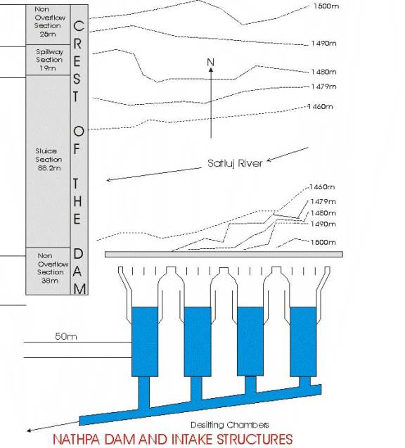
The proposed
working of the project
The Nathpa dam which is a concrete gravity dam proposed to
be of 60.5 m height is expected to divert 486 cumecs of water to the intake
structure on the left bank comprising four intakes. Each intakes are provided with independent trash rack with trash
racking machine located at the platform provided above F.R.L. to facilitate
cleaning of rocks. The intake structure
leads to the four disilting chambers through an independent shaft with vertical
life gate to control the flow of water.
A continuous skimmer wall top at El. 1468.73 m extending upto dam, also
has been proposed in front of all the four intakes to restrict the entry of
sediments into the intake pool.
The underground desilting complex meant to exclude sediment
particles above. 2 mm to enter the
headrace runnel (H.R.T.) is the largest underground complex in the world. Each chamber is provided with a 3 m wide
collection trench in the center running along its length. The hopper portion of the chamber slopes
towards this trench. The sediments from
the collection trench are expected to flow down to the flushing conduit running
below this trench and finally dump into the river through a main flushing
tunnel.
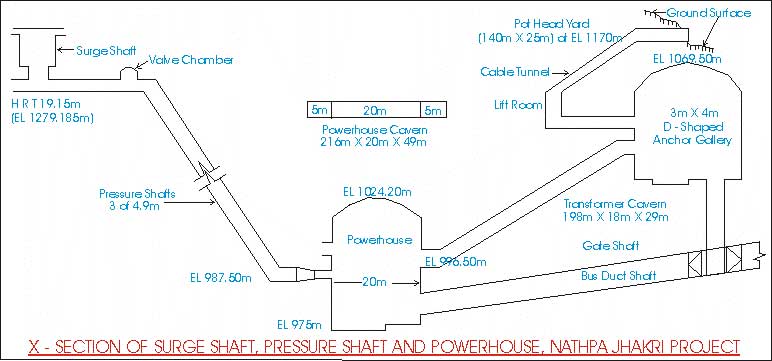
This cleaned water is then fed to the H.R.T., which is
proposed to be of 10.15 m diameter and circular in cross section. The HRT, which is 27295 m long runs from
Nathpa to Jhakri and is one of the world's largest power tunnels. This power tunnel is connected to the
penstock through a main surge shaft to control the excess pressure of water. The surge shaft located at the intake of the
penstocks has a 21 m diameter and is a vertical opening of 225 m height and
also happens to be the deepest surge shaft in the world.
The penstock comprising three pressure shafts of diameter
4.9 m and length varying from 619 m to about 660 m would take off from the
surge shaft at an angle of 450 to the horizontal. These would be lined with high tensile steel
corresponding to ASTM-A- 577 of thickness varying from 32 mm to 60 mm. Each pressure shaft will be made to bifurcate
into two branch tunnels of 3.45 m dia. varying in length from 43 m to 65 m near
the powerhouse to feed the six generating units inside the powerhouse. Butterfly valve housed in a valve chamber
are proposed in the horizontal reach to pressure shafts for repair/maintenance
without dewatering the head race tunnel.
The six tunnels are made to feed six turbines placed in an underground power house cavern of internal dimension 216 m x 20 m 40 m located 200 m below the natural surface level. The powerhouse will have an arched roof with concrete lining and shall house six generating units each of 250 MW. The water from the turbines are diverted through the six draft tubes to the tail race tunnel (T.R.T.) of 10.15 m dia, with circular cross-section, which carries the water back to the river. The power house cavern is integrated with the transformer cavern of size 198 m x 18 m x 27 m, which also houses an underground SF6 Switch-Gear. Figure gives a cross section of the surge shaft, pressure shaft and the powerhouse.
GEOLOGY OF THE
AREA
Stratigraphy
The whole project is situated in the lesser Himalayan zone
and comprises the Precambrian meta-sedimentary sequence of the Jutogh
formation, overlying the Wangtu gneissic complex, which also forms the
basement. The Wangtu gneissic complex
was considered to be a part of the Sarahan formation containing the Jutogh
formation (Jhingran et. al. 1950 and Tewari et.al., 1978). Kakar (1985, 1988) considers the stratigraphy
to consists of a basement of Wangtu gneissic complex, in thrusted contact with
Karcham group along the karcham thrust.
A summary of the stratigraphy of the area is given in table 1.
Geomorphology
The topography of the area is extremely rugged and bears a
dendritic drainage pattern. Steep
gorges formed by the Satluj river and other minor rivulets are also seen. The
Satluj river flows at 1460 m above M.S.L. at Nathpa and is fed by the Bhaba,
Baspa and Spiti rivers upstream of Nathpa.
Lake Mansarover forms the main feeder to this river upstream of
Nathpa. Lake Mansarover forms the main
feeder to this river system. In general the area exhibits steep slopes due to
extensive down cutting by the turbulent water of the Satluj River. Many hanging valleys formed by the various
rivulets are also noticed. The general flow direction of the river is east to
west which is conformable to the general strike direction of the Himalayas.
Table 1: Summary of the
Stratigraphy of the area
|
Sharma
(1976) |
Tewari
et.al., (1976) |
Kakar
(1985) |
|
|
|
Lower Haimanta formation |
(In phystcal order of super position) Meta sediments
Rakcham Granite |
Haimant Group (LR) |
(Stratigraphic order) Lower low grade schists and states. Gnesses grading into kyanite garnet
schists |
|
|
|
Madi Gneiss |
SUMODH FAULT |
|
|
|
|
|
|
Coarse psammitic Gneiss 800 m Granitic Gneiss 500 m.
Branded Gneiss with Kyanite |
|
|
7500 M. (inner crystalline unit) |
Mehbar Gneiss |
Karcham Group |
Psammitic Gneiss 3500 m. Graphite Schists 5000 m. Rampur Quartzite 50 m. |
|
|
|
Jutogh formation Chail formation Shatul Gneiss Rampur Formation Wangtu gneiss |
KARCHAM
THRUST |
|
|
|
(Outer crystalline unit) |
||||
|
Wangtu Gneissic (Up) Complex |
Interlayeredporphryoblastic aGneiss and Banded 7800 m. |
|
||
Local Geology
The major rock types of the area are augen gneiss,
quartz-biotite schist, amphibolites and some pegmatite lenses at places.
Augen gneiss: It is essentially a two feldspar, two mica (mainly biotite)
gneiss, with a porphyroblastic texture, which at places are mylonitic. The foliations are defined by the micaceous
layers, which flow around the augens.
The elongation direction of the augens defines a strong stretching
lineation. The shape of the augens
varies from nearly round to lensodal at places, showing well drawn out
porphyroclast tails.
Quartz-biotite-schist: The schistocity has a strong domainal character with well
defined quartzose and micaceous layers.
The layers are tabular to lensoidal.
At places some biotite rich lenses are also seen. Strong stretching lineation on the foliation
plane is marked. At places the biotite
altering to sericite indicated by crumpling and high fissility is also noticed.
Amphibolites: The amphibolites are massive weakly foliated with a
prominent amphibole lineation, which appears to be a primary igneous flow
structure. The quartz, feldspar content
is very low and the rock is especially a biotite rich amphibolite. The amphibolites occur as narrow linear
belts in the outcrop and generally unparallel to the foliation of the country
rocks except at places they are at an angle to them.
Pegmatite: They occur both as concordant and discordant bodies and are
commonly associated with the gneisses.
These are present as tabular laths or as apophyses. Quartz and feldspar exhibit a graphic
texture. They also display two sets of
fractures.
Structure
The main structures present in the area include foliation,
lineation, joints folds and shear planes.
Foliation: There is a prominent metamorphic foliation ranging from
schistosity to gneissosity and have a general strike of E-ENE and a moderate
dip, towards N-NNW. Few representative
readings are given below :
800/350 – 450 ---- 3400
(At Jhakri) and 1000/400 --- 100 (At Nathpa)
Lineation: All the rock units have a prominent lineation. In the schists, it is defined by mica
alignment and elongation of the quartz grains.
In the gneiss, the elongation of the augens defines it. In the amphibolites, it is defined by the
alignments of the amphibolite’s grains.
Joints: There are three sets of joints, two of them are at right
angles to each other and the third, oblique to them is sub-vertical, and
resulting in wedge shaped block or rocks. The representative of the three joint
sets are:
850 - 870 /340 --420
–175 – 265 near
orthogonal
1930 – 2110/490 – 600
– 2830 – 307 joints
25 – 35/83 – 900 --- 1150 Sub-vertical joints
Folds: Minor pygmatitic folds along with local open fold are
present in the area. Some clear
exposures of pygmatic folding in the generosity is seen in an outcrop near
Manglad. The style of fold is broad, gentle open fold.
Shear Plane: Numerous small-scale shear planes are present throughout
the area. The altered horizons
consisting of clay and sericite within the rocks are good indicators of shear
zones. Shear planes are also marked by rich extensional structures like pinch
and swells, boudins and porphyroclast tails of the augens.
Pinch and
swell structures and boudins:
These structures are common and are parallel to the foliation. These are most abundant at the Nathpa dam site.
A review of the major folds and faults of the area is given
in table 2.
Table 2: A
view of major folds and faults of the area
|
Major Folds |
Axial trend |
|
1.
Tranda Anticline |
NE – SW |
|
2. Anticline on Indo-Tibet Road, near
sholding |
NW – SE |
|
3. Nigulsari Fold |
N200W-S200E
TO NS (near river Satluj) |
|
4. Watoli khad fold |
NW
– SE |
|
5. Khalandhar Multiple fold |
NE
– SW to NW – SE |
|
6. Jeori Sheep Breeding Farm Anticline |
ENE-WSW |
|
7. Ranikhad Anticline |
NW – SE |
|
8.
Bhatana Anticline Syncline |
N
700 W – S700 E |
|
9. Tywal Open Synform |
NW
– SE |
|
10. Manglad Khad Open Synform |
N300
W – S300 E |
|
11. Dhokkhad Anticline and Syncline |
N
– S |
Major Faults
1. Sungra covered zone, High angle fault with strike NW-SE
2. Fault east of Sholding khad, N250 E/700
– SE
3. Shalabag Fault, N400 W / 600 – N 500
E
Seismicity
The area of the project comes under the seismic zone IV and
falls between isoseismal VII and VIII, of the seismic map of India. Ground acceleration is equivalent to 98 to
100 cm/sec2. Earthquakes are sporadic and the strongest earthquake
witnessed by the area dates back to April 4, 1905 with its epicenter at 320
– 15'N and 760 15'E, having a magnitude of 8 on Richter scale.
Landslide
They are frequent either in the rainy season or during
snowfall in winters. The areas having
steep slopes, foliations, and excessive jointing are potential sites for
landslides. Landslides are most
frequent during the monsoons. The water percolates through the joints and other
planes of weaknesses and reduces the coefficient of sliding friction by pore
pressure. Thus, a small force or even
gravity becomes enough to trigger off a landslide. Other than this even some minor earthquake sometimes triggers off
landslides. Another important factor
that causes landslides are frost and wedge action in alternate snowfall and dry
seasons. This mechanical process
shatters the rocks and even a slightest movement makes them vulnerable to
sliding. Even the turbulent flow of the
river sometimes leads to excessive down cutting leading to slope failure of
rocks and thus causes landslides. Apart
from these mechanical causes alternation of biotite bands, or swelling of the
clay portion within mica due to percolation of water reduces the coefficient of
sliding friction, causing sliding. Blasting activities carried on in the area
for construction and other purposes also at times triggers of landslides.
GEO-TECHNICAL
INVESTIGATIONS
General
Geotechnical investigations mainly involve studying those
geological parameters that help in constructing the various engineering
structures like dams, tunnels etc.
Structures like dams or tunnels depend mainly on the lithology on which
they are constructed. The type of rock,
its quality in terms of porosity, permeability and structures decide as to what
should be the nature of support of structure.
During the course of the work different structures like dam site, the
seven edits opened up for constructing the H.R.T., the power house and the
surge shaft were visited and various geological parameter and the resulting
preventions were recorded. A detail of
all of them are presented below:
Some Important
Factors
Joint Spacing
The joints are most prominent in the gneisses. Two sets of joints are fairly consistent
over the whole region and the third set is well developed at few places, Nathpa
dam site being one of them. The attitude,
spacing and nature of the prominent joints of the area are given in table 3
Table : 3
|
Sl. |
Attitude |
Spacing |
Nature |
|
1. |
N-S
to N200 E-S200 W/ or sub vertical |
2/
meter or less |
Tight,
occasionally clay filled, sheeted at places |
|
2. |
N 150E/350 – W |
5/Metre |
|
|
3. |
NE-SW/750 – NW to
sub-vertical |
2/ meter |
Generally
open on the surface |
|
4. |
N 250E/450
– SE |
3/ metre |
|
|
5. |
NW-SE/Sub vertical |
1/ metre or less |
Not
well developed everywhere close spacing resulting in sheeting. |
Joint spacing can be studied in conjunction with foliation
and other structures on a geological wall log, which consists of projections of
structures at a given elevation. Such a
geological wall log has been prepared for part of a tunnel, designed to be one
of the transformer galleries of the Power House Complex.
Rock Quality Assessment – The 'Q' Value
This is one of the essential computations, prior to and
during tunneling, to select the right technology, depending on the rock class.
The quality of the rocks was assessed for an escape tunnel near the Power House
Complex.
RQD Equivalence = 20/m2 = 50%
J(n) (2 sets) = 4
J(r) (rough
undulating) = 3
J(a) (Filling) = 3
J(W) (Wet) = 1.0
SRF (One shear zone
at a depth >50 m) = 2.5
..Q = 50 x 3 x
1.0 = 5 which implies of rock.
4
3 2.5
Strain Rate Assessment
This is done where the rocks have failed in the tunnels, to
apply remedial measures commensurate with the strain rate. Stress acts on rock, which is unbalanced to
produce strain. The chief reason for the
caving in of the crown is the strain produced at the spring line due to the
overlying overburden induced stress not balanced by the supporting or casing
technology. Extensions of various
designs are calculated by employment to tape extensometer in common use because
of its accuracy and cheapness. It is
employed to calculate the strain rate on a daily basis.
Tunneling Technology
The 27.3 km. long Head Race Tunnel (HRT) is in focus, as it
requires technological brilliance to stabilize such a massive structure. The various facts that play important role
in applying the right technology are as follows :
i)
The most important
aspects to be kept in mind while tunneling is the disposition of the tunnel
with respect to the foliation and other planar discontinuities which are
potential slip structures.
ii)
The rock quality
plays a vital role in deciding the blasting procedure and tunnel support.
iii)
Overburden plays an
important role in deciding the blasting procedure and tunnel support.
iv)
Seepage and position
of the water table need to be considered.
If the seepage is temporary, then there is no problem. In case it is permanent, suitable treatment
is required.
Dam Site
The lithology of the dam site consists of jointed gneisses with lots of shear bands. The clay material is being excavated and the gaps grouted. Finally, the rocks are bolted and shotcreted to consolidate the wall rock. The left bank is less stable as the wall cuts across the foliation joint. There have been instances of slides on the left bank, primarily due to sheet induced slope failure. The reservoir crest is at EL. 1490.50 m and spillway crest is at EL. 1488.00 m. A profile along the dam axis show that the foliation dips towards the abutments along the left bank whereas they dip away from the abutment along the right bank thus suggesting a need for stronger support on the left bank.
For constructing the dam, a coffer dam is proposed upstream
which is expected to divert the water during off-monsoon season through a diversion
tunnel in the right bank, downstream of the dam site, to facilitate
construction work. Cable anchors are
also being installed which are expected to carry chilled concrete overhead so
that they can be dropped at a rate sufficient for the material to remain in the
fluid state in the air, which after being dropped will be immediately chilled.
The Adits
Seven edits are opened for construction of the H.R.T. and
other important structures mentioned above.
A detail of the adits is listed in table 4.
Table 4: A
detail of the Adits
|
Name of adit |
Length(m) |
Station at junction with HRT |
|
Inlet
Adit |
1062.00 |
996.00 |
|
Sholding Adit |
876.00 |
5668.00 |
|
Nugalsari Adit |
647.00 |
9665.00 |
|
Wadhal Adit |
842.00 |
16042.00 |
|
Manglad Adit (r.bank) |
682.00 |
22500.00 |
|
Manglad Adit (I.bank) |
668.00 |
23155.00 |
|
Daj
Adit |
775.00 |
26478.00 |
Rattanpur HRT
Here the rock type is quartz biotite schist with a prominent
foliation, attitude 2650/260 – 3550. The
mapped face has quartz boudins parallel to the foliation.
One set of joints at a high angle to the foliation is
present. The tunnel is parallel to the
strike of both the foliation and the joint, which is very unfavorable. As such,
it is proposed to open the crown first upto the spring level, apply the
requisite rock bolts and shortcretes and then open up the tunnel further down
up to the invert. The shape of the
tunnel will eventually be circular. A
portion of the tunnel has caved in, in this part of the HRT, due to overburden. The remedial measure consists of closer rib
spacing and use of wider steel ribs.
Approach
tunnel to Power House
This tunnel has a horseshoe shape design. The tunneling conditions are more favorable,
as the foliation plane is the face of the tunnel (figure). As such, the method employed here is
slightly different. The invert to
spring is first opened up (figure) and supporting pillars are simultaneously
raised till the spring level. The
spacing of the rib caging is wider here.
On the walls traces of foliations appear and hence rock bolting on the
walls are closely spaced.
Manglad HRT
Here the overburden is the least, but there is continuous
seepage along the crown. Due to low
overburden, the stress on the crown is less as compared to that on the walls
which gives rise to stability. A steel
jacket is proposed to provide support for tunnel in this section (figure).
EXTENSIOMETER
The extensometer is employed to measure rock movement. In this method, a hole is drilled in the
wall. A plastic casing job is done on
the drilled hole. The instrument is
inserted into this casing. The pointed end is anchored in the bedrock. A reference plate is fixed to the rock. The movement of the rock is quantified by
readings on this plate. The magnitude
and ratio of strain is calculated from this.
Dams of the world Top 10
storage dams Top 10
Hydrodams GAP project
(dam)
World commission on dams Dam report Risk
analysis for dam safety Dam failures
Dam failures-natural hazards Software in dam break analysis Engineering geol & dam links