BRIDGES
A bridge consists of a superstructure and substructure. The weight of the superstructure and the loads imposed on it are taken by the supports of the bridge and transmitted to the foundation. To design the foundation, it is necessary to know both the magnitude of the forces and also the manner in which they are transmitted to the foundation. From this part of view, there are three categories of bridges :
1.
The vertical loads acting on the superstructure
are transmitted vertically to the foundations.
2.
Besides the vertical forces transmitted to the
foundations by the supports, the horizontal thrust pushes
the supports outwards.
3.
The vertical forces are transmitted to the
foundations vertically, but for stability the superstructure has to be anchored to rock on a
large concrete mass, and there are forces that tend to pull out the anchorage.
The
superstructure may be steel, reinforced concrete, or timber. It rests on or is fixed to the abutments. Abutment refers to a terminal support of the
bridge. Obviously, a bridge has two
abutments, and the traffic has to pass over both abutments in order to enter
the bridge and leave it. The abutment
may be an embankment of variable height on merely the ground surface with
perhaps a little grading. Abutments
generally are made of concrete, plain or reinforced, although in some bridges,
other materials are used, e.g. steel or, in old bridges, rough ruble masonry. The concrete abutments sometimes are faced
with 'dimension stones'.
If
the bridge consists of several spans of equal or variable length, the
intermediate supports (between abutments) are piers. A multispan bridge may consist of a number
of mutually independent girders supported at both ends on the piers and
abutments, or a long girder may cover several spans ("continuous"
girder). In all cases of girders, the
girder must be allowed to move a little for temperature expansion. For this purpose, the girder should be fixed
firmly on an abutment or pier and placed on rockers or rollers on other
supports.
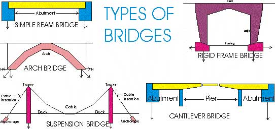
Figure
represents a cantilever
bridge with two piers and two abutments.
The piers essentially carry the weight of the superstructure, and the
structure may be so balanced that the load on the abutments is negligible. The
girders have protruding arms (cantilevers) and carry a relatively small, simple
beam at the center of the bridge.
Arch bridges may be
steel, concrete on timber. An arch
bridge may be provided with a tie that takes up the horizontal thrust, H,
caused by the arch instead of the abutments doing so. A rigid frame bridge may
be steel or of reinforced concrete and is commonly of one or two spans.
A suppression bridge
consists of two cables, generally sprung of strong wire, which rests on saddles
firmly fixed at the top of the steel towers.
The loaded cables have the tendency to pull the towers inward, and to
oppose this tendency; the cables are anchored either in natural rock or in
massive block of concrete that holds down the end of the cables.
Abutments of a Bridge
If
the bridge access is an embankment, the abutment has to hold it
back to prevent the earth from moving into and obstructing the waterway between
the bridge supports. The abutment has
to offer a seat for the superstructure and at the same time be a retaining wall
for the embankment. Designing swing abutments does this.

The
plan of footing for a beveled–wing abutment is shown in figure. The
straight-wing abutments are somewhat weaker than the beveled-wing; the wings of
the latter reinforce the straight retaining wall.
When
the land is inexpensive, U-shaped abutments can be used. In this type only the
central part of the embankment is contained between the wings, and the slopes
are permitted to fall outside.
Besides
these simple abutment types, there are a number of other arrangements serving
the same purpose.
Piers of a bridge
These
intermediate bridge
supports are built mostly of concrete with granite facing. Occasionally steel is used or even timber in
bridges formed by piles protruding over the high water level. As a rule, the longer the stream, the higher
the piers and the deeper the foundations.
However, in wide shallow rivers, the piers are generally low and
foundations rather shallow. Highway
piers are long perpendicular to the general direction of the bridge. Railroad bridges generally are much
narrower, their width depending on the number of tracks they have to
carry. Small bridges generally have no
piers but in rare cases may have one or two.
Figures
represent a solid concrete or masonry shaft for a medium –Size Bridge. It has triangular (or rounded) ends directed
against the current, though in many cases, the piers have symmetrical
ends. The pier is battered on all
sides, though in modern bridge-piers, the downstream end is often
vertical. The pier may be provided with
a starling, most of
which should be located below the high water level. The function of the starling is to regulate the passage of water,
and, particularly, to serve as an icebreaker in the spring.
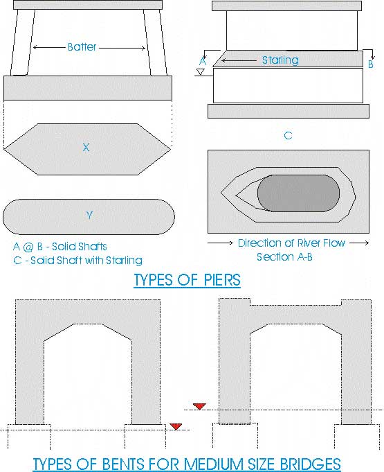
A
few types of hollow piers for medium sized bridges are shown in figures. In a long structure with a considerable
number of spans, piers similar to those shown in figures are generally
called bents. Piers for longer bridges generally are
hollow and somewhat similar to in shape to the dimumitive bents shown in
figure. They consist of combinations of
high vertical shafts, straight, stepped or circular (cylindrical) with portals,
and other architectural features.
In
the design of bridge foundations, the settlement of the bridge and its
stability should be considered. The total vertical load on the foundation of a bridge consists
of the dead load plus the vertical live load.
If the bridge supports stands on a spread foundation, the total load (in
pounds) divided by the area of contact of the foundation (in square feet) gives
the soil pressure in pounds per sq. foot on the base of
the support. The soil preserve should not exceed the value of the unconfined
compression strength of the underlying materials.
Stability
of the bridge is affected by lateral forces and scour (a type of water
erosion). The lateral forces, of which wind is the most important, essentially
cause an overloading of the foundation on the lee side. This overloading is of short direction only
and, practically, does not affect the settlement of the bridge, but in
exceptional, vary rare cases; it may cause the support to tip. The maximum shearing stress acting on the
supporting soil materials should not exceed their shearing strength, using
small safety factor.
Besides
wind, other lateral forces acting on the bridge are presence of the running
water, wave action, ice and drift presence, and shocks from passing vessels if
the piers are unprotected by special fenders of piles driven around the
pier. In railroad bridges, the
longitudinal forces, mostly due to braking of the trains, may be of
importance. For modern bridges supports
on deep foundations the lateral forces are of little consequences, except they
may be critical for weak timber piers.
Scour
When
the bridge supports and often a portion of the access embankments are placed in
a waterway, it becomes narrower. Thus scour is caused because the water
velocity increases and the bed deepens until some state of equilibrium is
reached. Scour may also be induced, by rectifying a meandering stream in soft
alluvial deposits. Such a rectification
is combined with an increase of the flow gradient (because of the shortening of
the distance) and hence in velocity. Scour may be observed also in stream under
natural conditions without any bridges. In all cases, scour is intensified
during the high water periods.
There
is no efficient method to prevent scour. One of the palliative methods is
placing riprap around a pier; another one is to drive piles under a pier to a
depth greater than required by stability of the pier. Piles thus driven, which
will be exposed between the periods of high water, should be protected against
dry rot, for instance by impregnation. Though the terms "scour" and
"erosion" are practically synonymous in geo-techniques, there is little
refinement in their usage, e.g. scour at the bottom of the channel and erosion
of the banks of the channel.
Abutment foundations:
In the geo-technical investigations for a bridge abutment, the influence of
water in scouring in softening and swamping the soil should be duly
considered. Abutments are built mostly
on spread foundations, though pile foundations also have been used.
Pier Foundations: The piers of a bridge are more subject to the action of lateral forces and scour than the abutments and often are founded on deeper foundations. There are water piers, permanently or periodically standing in water, and land piers, or via duet-type piers. The piers of the via duet type should be founded below the frost line in the same way as building facings, and if the highest ground water level is above the base of the facing, the resultant, decrease of the bearing power of the foundation should be taken into account by the designer when proportioning the pier. Water piers which stand in water only periodically should be founded below the frost line or at a level which ensures a good seat of the pier and safety from erosion during the high-water period, whichever of these two levels is lower. In any case, the bottom of the pier footing even for a small bridge should be at least 3 ft or so below the finished grade or the bottom of the stream.
Bridges of the world Structural Repairs -
Rogers Structural Investigations Ltd
The Bridge Project Bridge Photos Bridge Span Tables Longest Suspension Bridge