COFFERDAMS AND
CAISSONS
Cofferdams: In an engineering
structure, such as a bridge pier, has to be built in an area covered with
water, e.g. in the middle of a river, the area where the work has to be done is
surrounded by a cofferdam. A cofferdam
is a well made of earth materials, of steel or timber sheet piling, or a
combination of various materials. Under
actual working conditions, it is impossible to build a perfectly impervious
cofferdam and as such there is always some seepage though the cofferdam, and
the water has to be pumped out of the working area. Cofferdams also are used, to protect a working area against a
large influx of subsurface water.
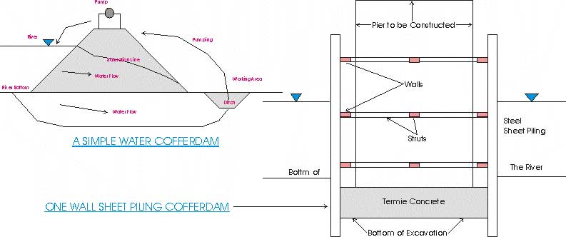
A
simple type of water cofferdam is shown in figure. Water seeps both
through and under an earth embankment built in the river. An essential point of the cofferdam is a
ditch dug within the working area and parallel to the embankment. The ditch acts as a center of attraction for
the flow lines of the seeping water.
The pumps standing on the embankment throw the water back to the river.
Sheet
piling used for the protection of the working areas may be of timber for water
depths up to 10 ft. or of steel of a great variety of cross sections. A type of one-wall sheet piling cofferdam is
shown in the figure.
The sheet piling is driven to a depth below the base of the proposed pier until
it is well embedded in the surrounding soil, and the material inside the
cofferdam is excavated by dredging.
Caissons:The
term 'caisson' literally means 'box', whereas a cofferdam is removed after the
structure is completed, a caisson remains in place and forms an integral part
of the structure. During the
construction period the caisson functions as a cofferdam. A box
caisson is a watertight timber or reinforced-concrete box having a
bottom but no top. It's use is
convenient when there is no excavation and the bottom of the river is more or
less level; a box caisson also may rest on top of piles. The caisson is constructed on shore and
floated to the site.
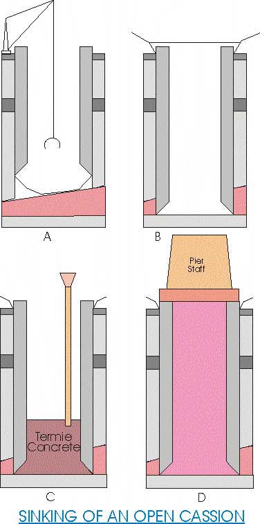
An
open caisson is a box without top or bottom, made of timber, metal, or
concrete. An open caisson has heavy walls and sharp wedge like edges which
allow it to sink with the aid of additional temporary loads and jets of water
while the inside material is dragged out. The sinking of an open caisson
proceeds at atmospheric pressure, and theoretically, there is no limit to the
depths of sinking.

When
it is not possible to excavate wet ground in the open, pneumatic caissons are used. A pneumatic caisson consists
basically of a working chamber and tabular shafts (generally two) provided with
air locks. One of the shafts has a
materials lock, which is used for removing muck from the working chamber; the
other has a man lock, which permits the labor force to travel in and out.
CROSSINGS AT VARIOUS REACHES OF A RIVER
An
example, of a stream originating in the mountains and flowing into an alluvial
valley will be considered.
It
the stream is crossed at an upper reach or at the beginning of the middle one,
a V-shaped narrow valley has to be spanned.
In such a case there is only a little alluvium in the stream, the latter
is not wide, and thus a one-span bridge with abutments on rock can be used.
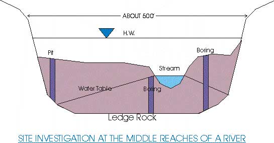
At
its middle reaches, the stream gradually approaches the character of a mature
stage. The cross section
of the valley is wider and is trough like. There are boulders, gravel and some
coarse sand on the shores.
If the freshet (high water) is abundant and the water level high usually a high (as in the figure), one span bridge is needed. The immediate objective is to disclose the configuration of the rock floor and the stability of the rock as a foundation material. The quality of the rock material in the cuts on both shores of the valley should be investigated. This rock material, together with alluvium in the valley, may be used for concrete and, in any case, for building the approach embankments to the bridge.
In
the cases similar to those shown in the figure, the transverse
gradient of the water table is probably from the stream rather than toward the
stream (inversed infiltration). The
water table may even be completely absent as in the case of the pit shown to
the left in the figure.
Crossing a lower stream reach
An
example of such a crossing with a relatively shallow rock floor is given in the
figure. Assuming that the valley has been found by
erosion of original limestone beds and is filled with alluvium, sand and
gravel, and boulders (left shore). The right shore is high and formed by sandy
and silty clays developed on eroded and weathered limestone. The following set of structures has to be
planned: (1) left-shore approaches to the bridge in the form of embankment on
the terraces (2) a large bridge with a part of supports in the flood plain via
duet or land piers and another part in the stream itself, and (3) a deep cut
through day on the right shore to connect the bridge with the adjacent
country. Accordingly the geotechnical
work consists also of three parts, the simplest one being the study of the
terraces on the left shore. Here,
simply auger holes will do (boring 1 figure).
A preliminary examination of the right shore slope should be made to
spot any possible sliding or fissility.
Emphasis should be laid on the study of groundwater conditions
(direction and discharge). If the
slopes of the cut will be in limestone, samples of the latter should be tested
for solubility.
Large
rivers in their reaches are very wide, and the general procedure for locating
borings should be as follows:
When
the position of the longitudinal axis of the bridge is established and the
abutments located, the topography of the river bottom along the bridge axis
should be obtained. In a wide river,
there may be channels or depression, which are unfavorable for the emplacement
of piers, and conversely sub aqueous islands ridges or outcrops may be suitable
for this purpose.
In
large navigable stream, the location of the piers may be controlled by the
large vertical and horizontal clearances that are required. A large span
covering the deepest part of the stream channel, with a considerable vertical
clearance (e.g. 30 ft) above the high water level, may be required for bridges
covering navigable streams. This
increases the height of the piers and, of more importance, increases the length
of the bridge. In this case, a bridge
proper degenerates into via duets on both shores of the stream. The abutments are thus moved far away from
the stream, often to an elevated dry locality with a simplification of
construction and no worry about proper location. A required vertical clearance also demands exceedingly accrete
settlement computations of the bridge support in the navigable channel; since
an excessive settlement may unduly decrease the clearance.
Crossing a river dose to its Delta
A
high bridge in this case always spans a navigable river with land piers on both
sides. Under certain geological
conditions e.g. when the river flows over a huge alluvial fan and it’s higher
than the adjacent. Locating, the bridge
would be extremely high; thus attempts should be made to locate the railroad or
the highway in a tunnel under the river.
Since a bridge crossing a river and it's delta is close to the shore
line, the possible slow movement of huge sand masses toward and along the shore
line should be considered. This
precaution is especially important if a bridge has to be founded on friction
piles. If the latter are too short,
they may move downstream and deform and twist the superstructure.
Civil Engineering Vs. Geology
Civil
engineers depend upon a proper appreciation of geology for their success and
efficiency. Civil engineers can assist geologist by allowing them to examine
excavations for study of parts of the earth's crust that otherwise would never
be seen.
Wherever,
the civil engineer is asked to plan, design, and construct there will be a host
of geologic considerations to be either accommodated or mastered. Environmental impacts within and around each
construction site will have been minimized, and judicious layout and design
will avoid creation of additional geological problems. The principles of geologic application to
planning do not vary, although the particular features of different sites
will. Planning begins with the
identification of the main geologic features that will influence the environmental
impact of design, construction and operation.
The general geologic setting, climate, site hydrogeology, water supply,
soils and a host of other features need to be considered. Seismic risks related to faults, landsides,
natural cavers and underground space pose an additional geologic problem. Once listed, geological features must be
considered individually on the basis of planning. Finally, site geology must be assessed as it is revealed by
excavation, to ensure that design assumptions are correct and that no unusual
or unsuspected features are present.
Civil
engineers have made significant contributions to the science of geology. All engineering geologists and civil
engineers connected with construction are constantly on the alert for
information that will contribute usefully to geologic on archaeological
knowledge. Every exploratory boring or
drill hole provides the civil engineer with what many geologists wish for, a
verification of the accuracy of deductions made from surface observations. Geotechnical
theory and a well-developed suite of laboratory testing procedures provide
almost untapped potential for geologic utilization.
The
art of seeing the significance of the surface geology of each site and of the
subsurface geology as revealed by the borings need to be developed. The geologic challenge lies in the art of
seeing the exact interrelationships of the geology of the site and the
requirements of the structure under design and of seeing the correlation of
what excavation actually reveals with what was expected.
Geological investigation for a medium sized
bridge
1.
Preliminary
investigation: Detailed and complete geological mapping.
2.
Hydrological
investigation:
a)
Basis of the stream:
Basin area, length, elevation, character including vegetation soil, steepness,
drainage including tributaries, existing dams and reservoir.
b)
Stage of the stream:
Elevations and seasons of high water, ordinary high water, velocities at
different stages.
c)
Estimated discharge:
At different stages, including the combined action of show thawing and rainfall
which vary often gives the maximum possible discharge; frequency of floods;
d)
Stream bed:
Character of the bed material upstream and downstream of the proposed site;
obstruction to the passage of water or natural tendency to scour or silting
around these obstructions; meandering tendencies and dental or channel
regulations should be used such as deepening, widening, constructions of levees
or bank protection.
e) Drifts or Debris: Character, amount and size; appropriate vertical clearance of the superstructure needed for the passage of drift or debris; spans that may be required for that purpose.
Bridges of the world Structural Repairs -
Rogers Structural Investigations Ltd
The
Bridge Project Bridge Photos Bridge Span
Tables Longest
Suspension Bridge