SPILLWAYS
Spillway is the term
opted to a dam appurtenance, which permits water to pass over or around the
dam, a concrete structure that conveys floodwater from upstream of the dam to
the downstream without dampening the dam or reservoir walls or toe of the dam.
·
Operates when the
water rises over the maximum water surface.
·
In the simplest type
– water is permitted to flow over the crest of dam – submerged dam.
Crest
gates
·
Permit opening and
closing the spillway.
·
May be automatic – by
means of float system – gates automatically open when the water reaches a
certain level.
·
May be manual.
·
In small dams –
sometimes closed by stop logs or flash boards.
Controlled
spillway – gates used
Uncontrolled
spillway – gates are not used.
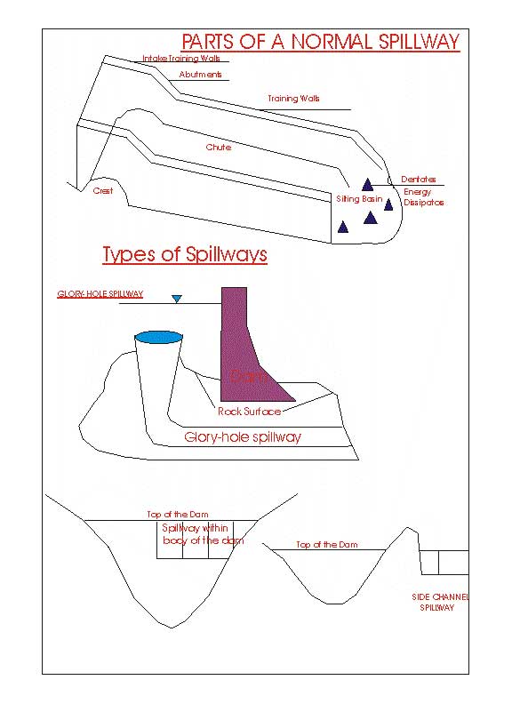
Types
of spillways - Rectangular or Trapezoidal in cross-section.
a) Normal/normal control spillway. Short cut channel followed by steep chute.
b) Side channel spillway –
where water flows over a weir that is perpendicular or at an acute angle to the
dam axis & is carried past the dam by an open channel or tunnel running
practically normal to the dam axis.
c) Shaft spillway – (morning
glory/glory-hole spillway) the excess water in the reservoir drops
vertically or obliquely into a funnel and is conducted downstream more or less
horizontally in a concrete pipe – generally under the body of the dam. Lip of the funnel is at the maximum water
surface.
d) Ski-jump
spillway – spillway has a projecting lip on the face of the dam (on
concrete dams. This lip causes the
water to "jump" into the air and land a safe distance downstream from
the toe of the dam – thus protecting the toe against erosion.
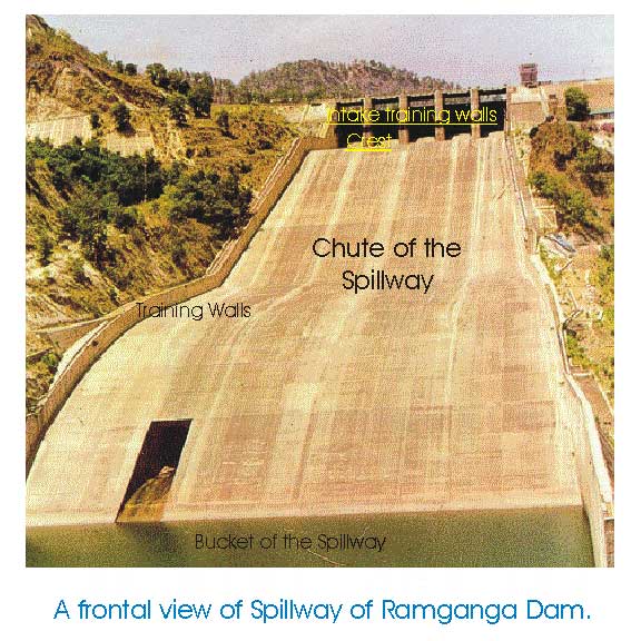
Parts of Spillway
Crest – highest part over which water flows.
Spillway chute – downstream portion of the spillway over which water flows.
Training walls - concrete walls on either side of the spillway chute
Intake training walls – training wall upstream from the crest.
Silting basin – deep basin located at the bottom of the chute and is
designed to reduce the turbulence of the spillway flow also referred as "spillway
bucket".
Dentates - the turbulence and energy of the spillway water sometimes
are further. Dissipated by means of
large, tooth like projection called as "dentate" or "energy
dissipaters".
Some
of these terms have been shown in Ramganga photograph.
Emergency
spillways – This type of
spillway is designed for extreme flood conditions – when normal spillway
capacity might be exceeded – excavation with a low weir across its crest, is
made in the rim. None of the other spillway appurtenances (chute walls etc.)
are constructed. - Damage to the foundation may be expected.

Outlet Works: (used in irrigation – to divert some of the water into
irrigation canals, municipal water supply system and hydroelectric plants).
Primarily
two types of outlets:
a) Tunnel type
– where water is carried in a tunnel lined or unlined through the abutments of
the dam.
b) Conduit type
– water is carried in a pipe through or under the dam.
Penstocks – for taking reservoir water to the hydroelectric
generators.
- Steel pipes of large diameter. Crossing the body of the dam.
- The powerhouse may be either just at the toe of the dam or
at a certain distance downstream depending upon the topography and economic
conditions.
Required geological considerations.
1.
A tight basin of ample
size
2.
A narrow outlet
requiring relatively small and economic dam with safe foundation.
3.
Opportunity for
building safe and ample spillway to dispose off surplus water.
4.
Available material to
construct the dam.
5.
Assurance that the
basin will not silt up in too short a time.
6.
Ample and available
water supply
7.
Use for stored water
or other adequate condition to justify the cost of the dam.
Reservoir Silting
River terminology
|
Watershed |
The
area that supplies a river with water and sediment |
|
Mouth
of the river |
Part
where the river joins the ocean/sea, lake or another river |
|
Reach |
Any
stretch or part of a river along its length upstream from the mouth |
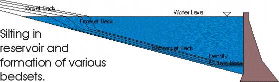
A
reservoir is formed upstream to a dam. – Sediment coming to the reservoir is
largely deposited in it and sooner or later – reservoir is silted – filled up
with sediment and the usefulness of the dam is lost. The presence of the dam retards the natural flow and hence the
water level in the reservoir is not horizontal but its surface is slightly
curved (Backwater curve). When
the river flow reaches the reservoir the flow velocity decreases and coarser
particles such as sand are dropped close to the entrance. The beds formed this
way are called foreset
beds.
Fine
sediments are settled slowly across the area of the reservoir. These are known
as bottom set beds. Foreset beds obstruct the flow still forthcoming from the upstream and
formation and propogation of topset beds occur. As time goes on the foreset beds advance into the reservoir to form higher &
higher slopes, which because of its height will not stand so steeply as the
slopes formed earlier. Hence the high
slopes of the foreset beds have to flatten out and cover a part of the
previously laid bottomset
beds. This causes an intermixture
of coarser and finer sediments at the bottom of the reservoir.
The
location of future silt deposit in a reservoir can often be predicted.
A) Sediment will deposit near the dam if;
i. The
reservoir water surface is at low elevation
ii. There
is high percentage of clay to fine silt size
iii. The reservoir is short and has a steep slope to the original
valley floor.
iv. There is little or no vegetation near
the head of the reservoir
v.
The dam has small
outlet at higher elevation.
B) Sediment will
deposit at the head of the reservoir it;
i. The conditions are converse to above.
Reservoir life: Reservoir capacity expressed in acre/cu.ft [1 acre ft. =
43.560 cu.ft]
Factors to
estimate the life:
·
How long it will
continue to store a useful amount of water - length of time the water stays in
the reservoir before being used.
·
The rate with which
the sediment accumulates from year to year and is not removed by natural
devices.
·
If the storage space
become less – these is an increase in the rate at which fine sediment leaves
the reservoir.
·
Silt at a high level
in the reservoir – removable by dredging (though costly) silt in live
storage. Silt in dead storage (low
level) cannot be removed.
·
Reservoir life can be
extended by sluicing operations the outlet gates are opened at appropriate
interval and the high velocity flows carry some of the sediment downstream.
·
If this is timed to
intercept gravity underflows – the sediment removal can be very efficient.
However, it is ineffective about the sediment, which is already settled.
Trap Efficiency: is the % of total
inflow of sediment retained in a reservoir (per unit time)/year. It depends
upon the ratio between storage capacity and inflowage of reservoir, the age of
the reservoir, slope of reservoir basin, the type & method of operation of
outlets, the and grain size of sediment and its behavior under different
conditions.
Trap Efficiency (T.E.) = Si – So -------
(i)
Si
Si – acre/ft of
silt that enter reservoir every year
So
– acre/ft of slit that leaves reservoir every year
Reservoir
sediment load Tons/ acre/ft (Taf)
= Unit
wt. of sediment p.c.f. x 43,560
2000
Total
acre ft of sediment = total tons of
sediment
Taf
![]() Reservoir life RL = C C Putting the value in (i)
Reservoir life RL = C C Putting the value in (i)
![]() Si x T.E. or Si-So
Si x T.E. or Si-So
C
– Proposed reservoir capacity in acre ft.
Dams of the world Top 10
storage dams Top 10
Hydrodams GAP project
(dam)
World commission on dams Dam report Risk
analysis for dam safety Dam failures
Dam failures-natural hazards Software in dam break analysis Engineering geol & dam links